A camera could identify a colored target, but real hardware added latency, noisy centroids, backlash, and high transient servo current.
Computer VisionEmbedded ControlMechatronics
Project 02 / Controls
Autonomous Object Tracking
A two-axis tracking platform that turns live visual error into physical motion—linking webcam perception, OpenCV processing, an ESP32, and a pan-tilt servo mechanism in one feedback loop.
2Controlled axes
2MG996R servos
1Live camera feed
D4 / D5Servo outputs
01 / Objective
Keep a moving target centered.
The project closes the gap between software perception and real hardware. A webcam observes a colored target, the vision pipeline determines where it sits relative to the center of the frame, and the pan-tilt mechanism moves to reduce that error.
The central engineering challenge was not simply detecting the target—it was coordinating image processing, embedded commands, actuator power, and mechanical response well enough to create stable, useful tracking.
02 / Engineering challenge + impact
The project in STAR form.
Create a stable two-axis system that converts live image-space error into repeatable physical tracking.
Integrated OpenCV perception, independent pan/tilt PID loops, ESP32 commands, and a dedicated 6 V actuator rail; then tuned on the mechanism.
Delivered a working closed-loop tracker and isolated actuator speed, backlash, and prediction as the next performance levers.
My contribution
Integrate perception, control, and hardware.
I developed the end-to-end tracking system, connecting the computer-vision pipeline to the embedded pan-tilt assembly and tuning the response around real actuator behavior.
- Built the Python/OpenCV target-detection workflow
- Converted image-space error into independent pan and tilt updates
- Configured the ESP32 interface and two-servo actuation
- Assembled the breadboard power distribution and common-ground topology
- Iterated on response to reduce overshoot, hunting, and visible jitter
03 / Closed loop
See. Measure. Correct. Repeat.
Observe
The webcam captures the target inside the image frame.
Locate
Python and OpenCV isolate the target and estimate its center.
Correct
Pixel offset from frame center becomes a pan-and-tilt command.
Actuate
The ESP32 drives both servos and the next frame verifies the response.
The camera is both the sensor and the final check: every new frame measures whether the previous motion reduced the target error.
04 / PID control
Turn pixel error into controlled motion.
Independent PID loops govern pan and tilt. Each loop compares the detected target center with the image center, then converts that pixel error into a servo correction. Keeping the axes separate made the controller easier to tune while still producing coordinated two-dimensional tracking.
eₖ = target center − frame centeruₖ = Kₚeₖ + KᵢΣeΔt + Kd(eₖ − eₖ₋₁) / ΔtApplied independently to pan and tilt
Hardware-in-the-loop tuning
The gains were tuned on the physical mechanism because camera latency, servo speed, backlash, and noisy centroid measurements all change the response seen at the target.
Establish response
Begin with proportional control and raise Kₚ from a conservative value until the platform follows motion quickly without sustained oscillation.
Damp overshoot
Add derivative action gradually to slow the response near the target and reduce overshoot, hunting, and rapid direction changes.
Remove residual bias
Introduce only a small integral term when friction or imbalance leaves a persistent offset, with limits to prevent integral windup.
Practical guardrailsCenter deadband prevents reactions to single-pixel noiseOutput limits keep commands inside the servo travel rangeCommand smoothing reduces abrupt frame-to-frame motion
05 / Electrical architecture
Separate actuator power. Shared reference.
The universal adapter is set to 6 V and powers both MG996R servos independently of the ESP32 rail. All grounds remain tied together so the D4 and D5 control signals share the same electrical reference.
Power path6 V supply + → both servo VCC inputsSupply − → both servo grounds + ESP32 groundSignal pathESP32 D4 → first servo signalESP32 D5 → second servo signal
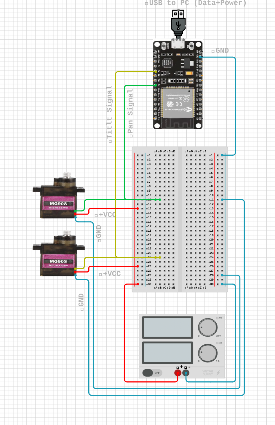
Wiring summary
FunctionConnection
Common groundSupply − → ESP32 GND → both servo GND pins
Servo powerSupply + → both servo VCC pins
First servo controlESP32 D4 → first servo signal
Second servo controlESP32 D5 → second servo signal
06 / Hardware
A compact, modular test platform.
Webcam
Captures the live scene and closes the visual feedback loop.
ESP32
Generates independent pan and tilt commands on D4 and D5.
2× MG996R
55 g high-torque servos provide two-axis actuation; each is rated at 2.5 A stall current at 6 V.
45 W supply
The selectable universal AC adapter is fixed at 6 V for the servo rail.
Breadboard + wiring
Distributes external power and establishes a common ground.
07 / Engineering takeaways
Good tracking is a systems problem.
Lighting matters
Color-based tracking is fast and explainable, but its reliability depends on contrast, threshold selection, and environmental lighting.
Speed versus stability
Higher proportional gain improves response but can amplify image noise and servo chatter. Derivative damping, a center deadband, and smoothed commands create more stable motion.
Power is part of control
Separating logic and actuator power prevents electrical transients from undermining an otherwise sound control strategy.
08 / Future iterations
From prototype to autonomous platform.
Actuator upgrade
Use faster, lower-backlash servos to reduce lag and small-angle jitter.
Response refinement
Measure settling time and steady-state error, then retune filtering, deadband, and command rate.
Predictive tracking
Estimate target velocity to lead motion and maintain lock through short occlusions.
UAV / GNC path
Adapt the visual-servoing loop to autonomous inspection, target following, and relative-navigation studies.
09 / Bill of materials
The complete prototype stack.
ComponentQty.SpecificationSystem role
ESP32 development board1Dual servo signal generation on D4 and D5Embedded control
MG996R servo255 g · 6 V · 2.5 A stall current eachPan and tilt actuation
Universal AC adapter145 W · selectable output set to 6 VDedicated servo power
Webcam1USB video inputLive target sensing
Solderless breadboard1Shared power distribution railsPower and ground routing
Jumper wires1 setSignal, VCC, and ground connectionsSystem interconnect